Automatic Boresight Calibration
in HIPS and SIPS
Borrowing adjustment techniques from the Lidar industry, the new Multibeam-IMU Automatic Calibration (MIBAC) algorithm developed by CIDCO is now available in HIPS™. The Automatic Boresight Calibration tool is designed to simplify both survey planning and post-processing for calibration requirements, requiring fewer survey lines in the field and providing a repeatable, robust calculation of the boresight angles between the IMU and sonar in post-processing in just a few clicks. The algorithm also provides immediate feedback to the processor on the quality and confidence of the calculation.
Efficient Survey Pattern
The new routine for auto-calibration requires a modification to existing traditional patch test survey line patterns. In this case, reciprocal and overlapping lines should be run up/down a smooth slope (minimum 10 degrees) such that the outer swath edge falls approximately at nadir for the adjacent run line. Put another way, two reciprocating line pairs up/down a slope with 50% overlap. Objects such as wrecks should be avoided.
 New Survey Pattern for Automatic Boresight Calibration
This pattern of 4 lines is easier to plan and execute versus the traditional patch method, which typically requires 5-6 lines for a full calibration. A dual-head calibration can also be accomplished in just 6 lines, where a traditional dual-head patch test would take at least 7.
Easy Boresight Calculation
Once the survey work is complete, the data is imported in to HIPS using standard techniques. The Automatic Boresight Calibration algorithm is executed using a single dialog box, where the user simply verifies the lines to use for the computation before executing the algorithm. The computed values are then presented to the user with a confidence measure (i.e. the standard deviation for each boresight angle adjustment). The result can then be applied directly to the HIPS vessel configuration and optionally output to a textual report.
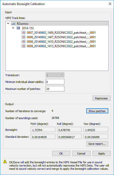 Dialog for Automatic Boresight Calibration
Robust Boresight Estimation
The boresight calculation is fully automated for the user. The incoming raw data is first geo-referenced, before the survey area is broken into small, variably sized, discrete regions called patches based on data density, uniformity and planarity. Each patch is evaluated for its sensitivity to each component of the boresight, namely pitch, roll, and yaw. These observability criteria are then combined, and those patches with the best observability (higher is better) for all 3 boresight components are selected for the calculation.
With the selected patches, an iterative least-squares method is applied to determine the final boresight values shown in the dialog.
The "patches" generated from the data, including those selected for the boresight computation, can be visualized in a 3D environment to ensure that the survey contains suitable data.
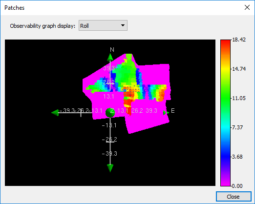 Observability for Patches: Roll
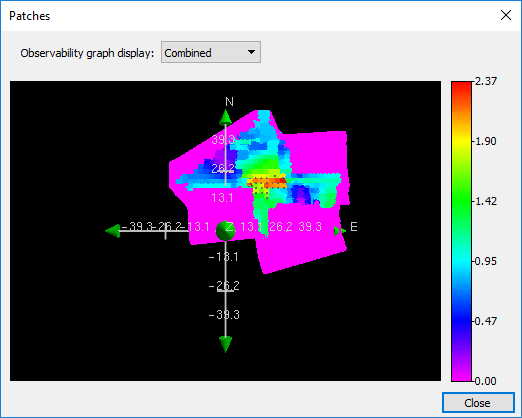 Observability for Patches: Combined
Analysis Tools
A Root Mean Square (RMS) Error layer can now be added to any gridded surface. This layer provides information that is similar to the Standard Deviation, however the RMS Error calculation measures the point distribution relative and orthogonal to an inclined plane extracted at each node in the surface. This is useful for evaluating the point distribution without the influence of slopes.
For Automatic Boresight Calibration, a comparison of the RMS error layers before and after the adjustment provides immediate insight into the effectiveness of the adjustment.
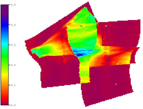 RMS Error before Automatic Boresight Calibration
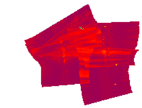 RMS Error after Automatic Boresight Calibration
To learn more about this new tool, watch this short and informative video.
Further Reading
The Automatic Boresight Calibration tool is based the work of Nicolas Seube and Rabine Keyetieu "MultiBeam Echo Sounders-IMU Automatic Boresight Calibration on Natural Surfaces".

